
Building an All Apps Organization in VMware Cloud Foundation 9 through VCF Automation is often presented as a simple workflow. In reality, the UI makes it look easy, but what determines success is how the platform is designed underneath.
Quick Start can stand up a working environment in minutes, but it does so by making decisions for you. Those decisions include how much capacity is assigned, how networking is inherited, and how resources are exposed to the organization.
That may be fine for a demo.
It is not fine for a real platform.
This article walks through what actually matters when building an All Apps Organization in VCF Automation 9. Rather than focusing only on what to click, the goal here is to explain the design decisions behind:
- regions and how they map to infrastructure
- quota and why it controls everything downstream
- storage and VM class exposure
- and why manual setup is the only approach that gives you real control
All screenshots used in this article have been sanitized to remove environment specific identifiers while preserving functionality and workflow.
Starting Point: Accessing VCF Automation #
Before any organization or infrastructure configuration begins, everything starts at the VCF Operations interface where VCF Automation is deployed and managed.
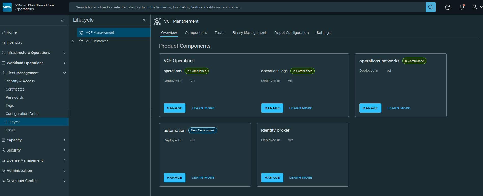
From here, Automation is already deployed and available as a service within the VCF platform. This is important context, because we are not installing Automation itself. We are working on top of an already deployed platform and moving into the provider configuration workflow.
Logging into the Provider Management Portal #
To begin configuring organizations, we need to access the Provider Management context of VCF Automation.
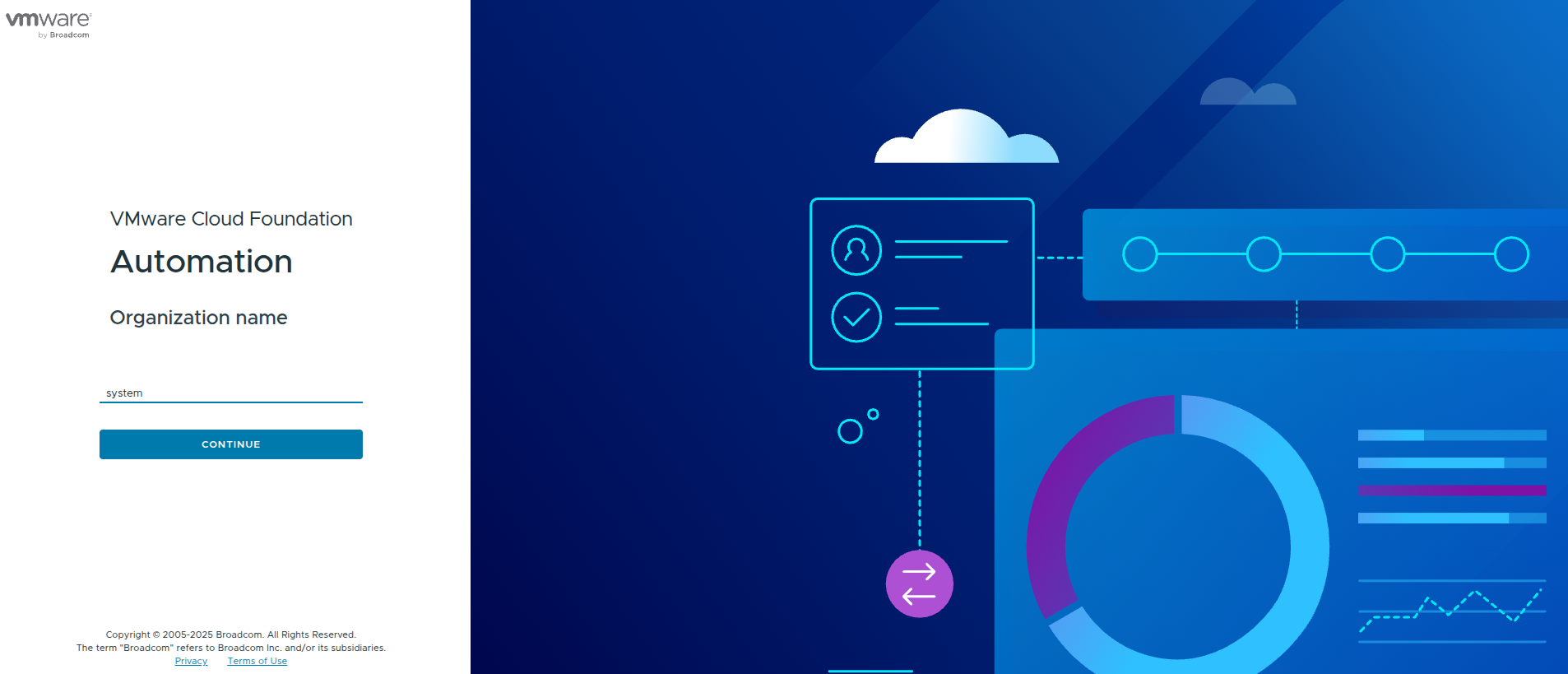
At this stage, the system is asking for the organization context. For provider-level configuration, this is done through the system organization.
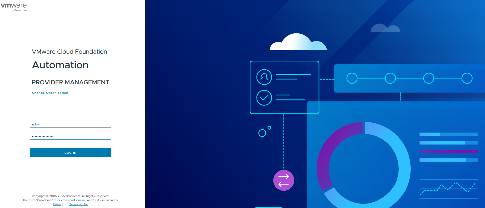
Once authenticated, this places us in the provider role where we can define:
- regions
- organizations
- quotas
- networking constructs
This is a key distinction early on.
The provider portal is where infrastructure is defined.
The organization portal is where it is consumed.
First Look: Quick Start vs Manual Setup #
Once logged in, VCF Automation presents two paths:
- Quick Start
- Manual Setup
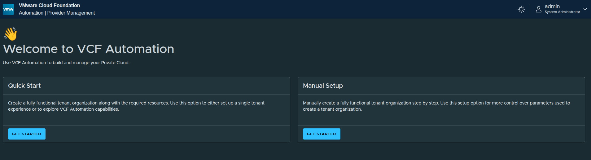
The platform is intentionally guiding users toward Quick Start for simplicity, but there is an important takeaway here.
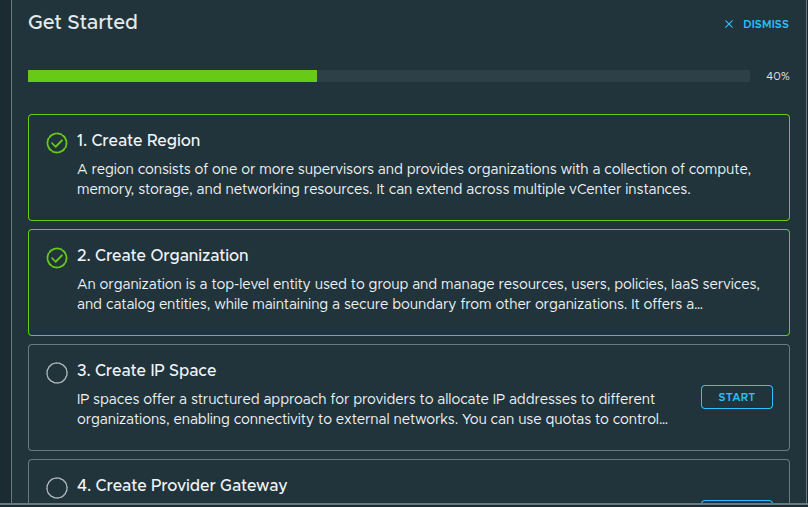
Why Quick Start Exists #
Quick Start is designed to:
- rapidly create a functional organization
- automatically configure regions, networking, and quotas
- allow immediate testing of platform capabilities
However, it comes with tradeoffs.
Why Manual Setup Matters More #
Manual setup allows you to control:
- how regions are defined
- how much capacity is allocated
- how IP space is designed
- how networking is connected
That difference becomes critical in real environments.
Quick Start is useful for understanding the flow.
Manual Setup is what you actually use in production.
Walking Through Quick Start (For Context) #
Even though the final implementation uses manual setup, it is still useful to walk through Quick Start briefly to understand what the platform is doing behind the scenes.
Organization Creation #
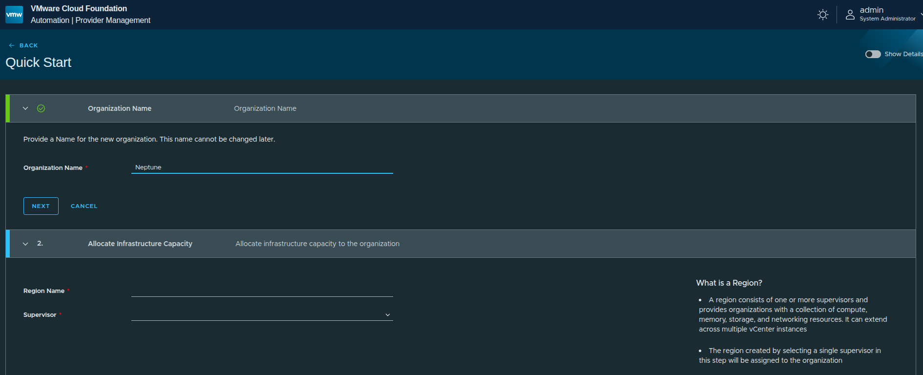
The first step is defining the organization name.
In this case:
Neptunewas used
This becomes the identifier for the organization and is tied to how users will later access it.
Region and Supervisor Selection #
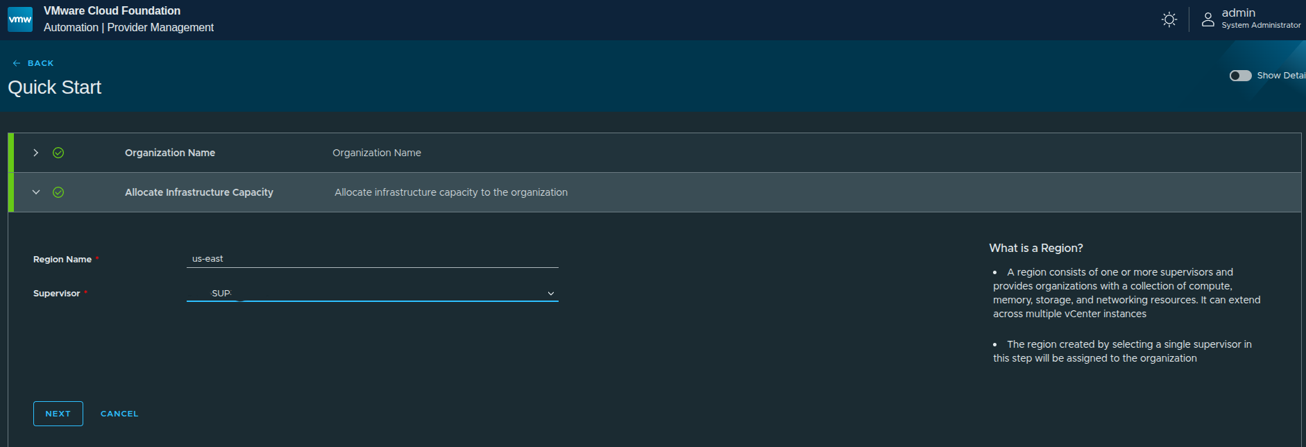
Next, the workflow asks for:
- Region name →
us-east - Supervisor → selected from available supervisors
A region represents a collection of infrastructure resources backed by a Supervisor.
This includes:
- compute
- memory
- storage
- networking
In this walkthrough, only US East is configured.
Storage Class Selection #
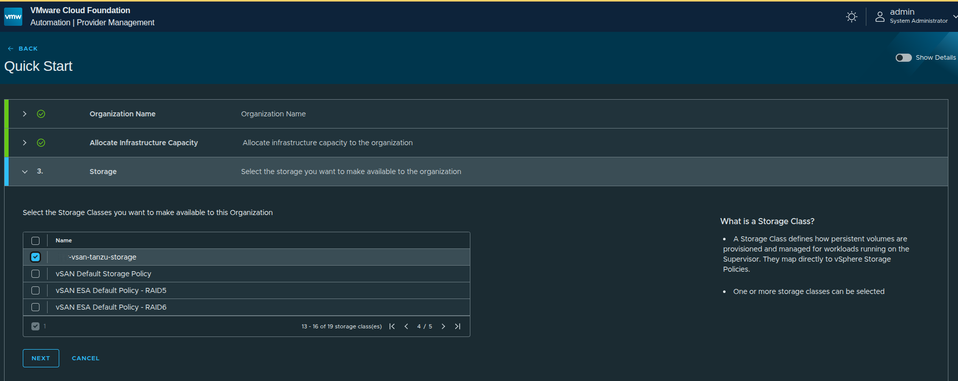
Storage classes are pulled directly from vSphere storage policies.
This mapping is important:
- what you select here determines what storage tenants can consume
- it directly ties Kubernetes and VM workloads to vSphere-backed storage
In this case, a vSAN-backed storage policy is selected.
Review and Provision #
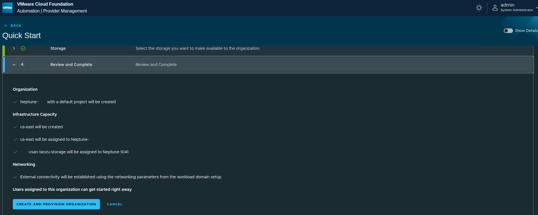
Before execution, the platform summarizes what will be created:
- organization
- region
- storage assignment
- networking (based on Supervisor configuration)
One key detail here:
Networking is automatically derived from the Supervisor configuration.
That means:
- external IP blocks already defined on the Supervisor will be reused
- no custom IP space is defined during Quick Start
- no provider gateway customization is done
Why We Move Away from Quick Start #
Although it looks simple, Quick Start is doing a lot of work automatically:
- creating the organization
- creating the region
- assigning infrastructure capacity
- creating IP space
- creating provider gateway
- configuring regional networking
That is useful for understanding the flow, but it introduces limitations:
- full capacity is often assigned by default
- networking is not customized
- IP space is inherited, not designed
- quotas are not tightly controlled
That is why, after understanding the Quick Start path, the next step is to reset and rebuild the organization using the manual setup workflow.
That is where the real control and design decisions happen.
Enabling Advanced Capabilities with Feature Flags #
Before moving into the manual setup workflow, there is one additional step worth calling out: enabling feature flags that expose additional organization capabilities.
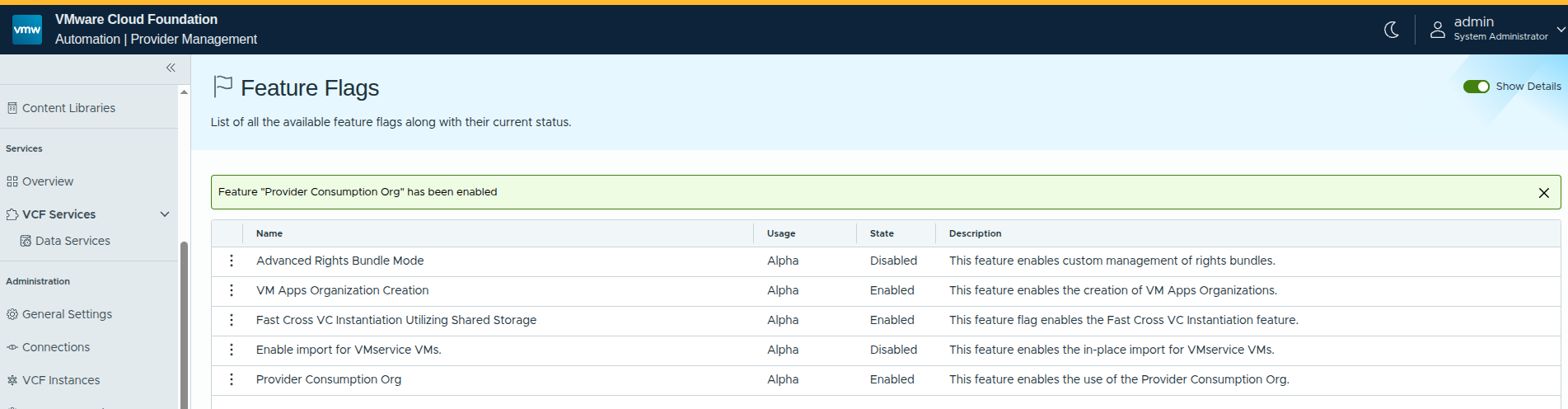
In this case, the Provider Consumption Organization feature flag is enabled.
Why This Matters #
By default, VCF Automation is focused on tenant-style consumption. Enabling provider-focused capabilities introduces more flexibility in how organizations can be structured and consumed.
From a design perspective, this becomes important when:
- building provider-managed environments
- sharing workflows and catalog items across organizations
- leveraging embedded orchestration capabilities at the provider level
The Provider Consumption Org specifically enables:
- provider-level organization patterns
- shared services across multiple tenants
- deeper integration with automation workflows
This is not required for basic deployments, but it becomes highly relevant in real-world architectures.
Creating the Region and Assigning Quota #
With the platform prepared, the next step is to begin building out the infrastructure manually, starting with the region.
A region represents a logical grouping of infrastructure resources backed by a Supervisor. This includes:
- compute
- memory
- storage
- networking
These resources are later exposed to organizations through quota and policy assignments.
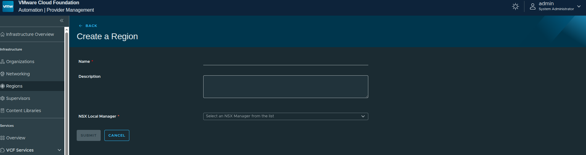
Defining the Region #
The first step is assigning a name and selecting the NSX Local Manager.
In this walkthrough:
- Region Name:
us-east - NSX Local Manager: Workload domain NSX instance
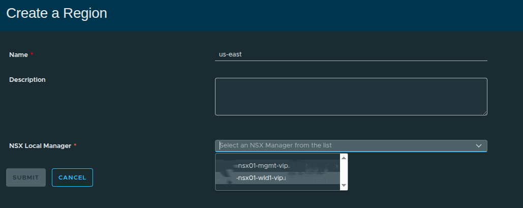
Selecting the NSX Local Manager is important because:
Supervisors can only be included in a region if they are connected to the same NSX instance.
This determines what infrastructure is even eligible to be part of the region.
Associating the Supervisor and Storage #
Next, the region is tied to a specific Supervisor and storage classes.
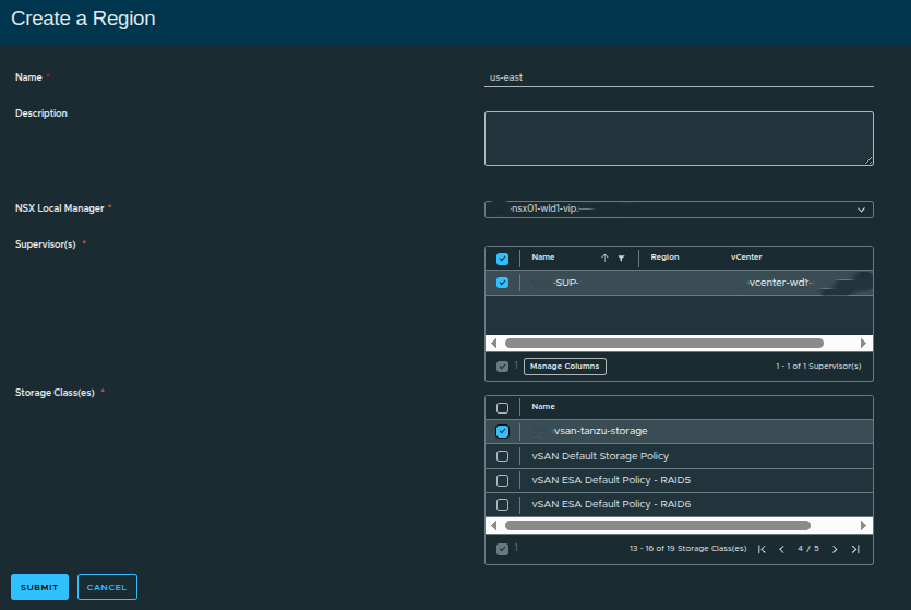
Here:
- Supervisor:
SUP - Storage Class: vSAN-backed policy
The storage class maps directly to vSphere storage policies, which means:
- what you select here becomes available to workloads
- it directly controls how storage is consumed downstream
If multiple storage tiers exist, this is where you expose them to the region.
Why Regions Matter More Than They Appear #
Although simple in the UI, regions are foundational to how VCF Automation organizes infrastructure.
A region:
- defines where workloads can run
- groups infrastructure into consumable boundaries
- becomes the scope for quota and networking
If the region is not designed correctly, everything built on top inherits those limitations.
Assigning Region Quota #
Once the region is created, the next step is assigning quota. This determines how much of the region’s resources the organization can consume.
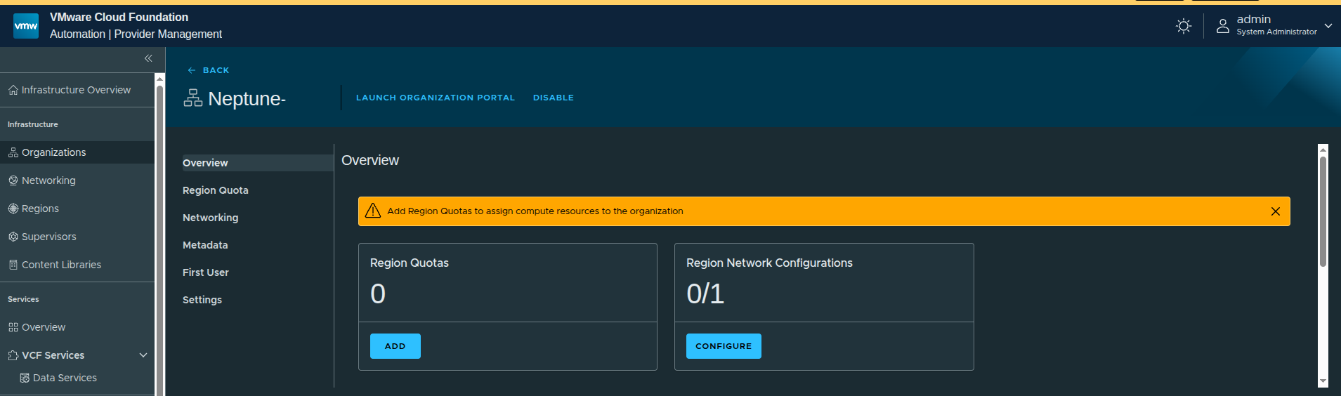
At this point:
- no quota is assigned
- no networking is configured
This is expected. Without quota, the organization cannot consume resources.
Creating the Region Quota #
To begin, select the region and associated Supervisor.
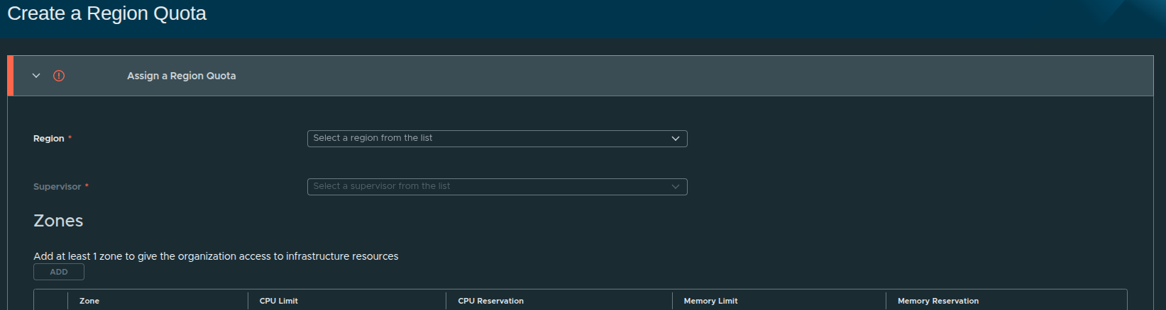
In this case:
- Region:
us-east - Supervisor:
SUP
Adding a Zone #
Each region must have at least one zone.
A zone represents a grouping of infrastructure resources, typically aligned to a cluster or availability construct.
A region without a zone cannot provide resource access to an organization.
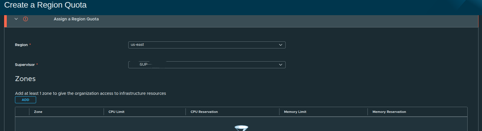
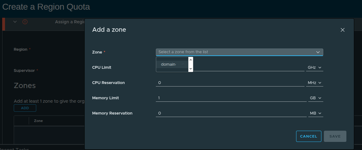
Defining Resource Limits #
When adding a zone, resource limits are defined.
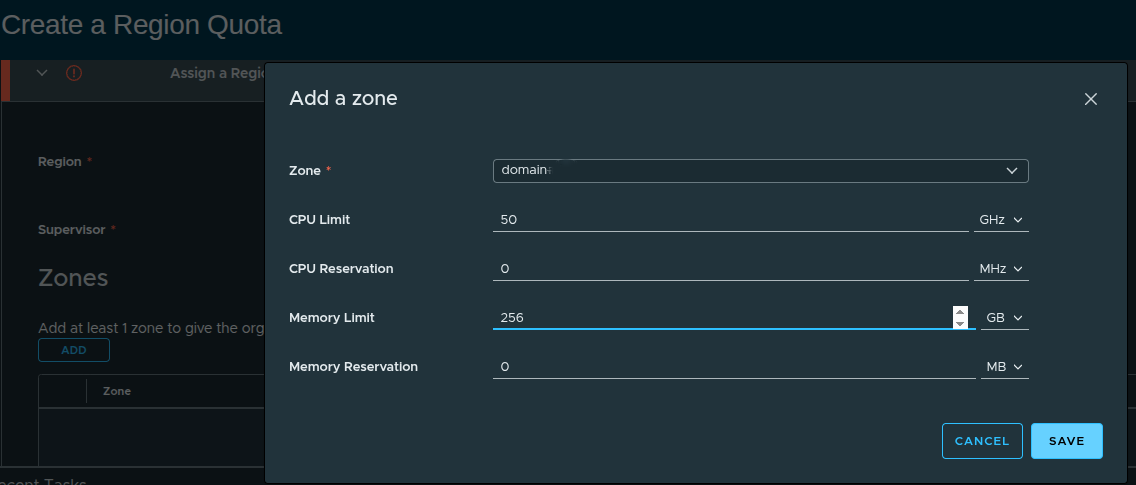
Example configuration:
- CPU Limit: 50 GHz
- CPU Reservation: 0 MHz
- Memory Limit: 256 GB
- Memory Reservation: 0 MB
These values define how much capacity the organization can consume.
Reservation vs Limit #
There is an important concept here:
- Limit = maximum usable capacity
- Reservation = guaranteed capacity
If you plan to use guaranteed VM classes, you must define reservations here.
In this walkthrough:
- only limits are defined
- reservations are intentionally left at zero
This aligns with a more flexible, best-effort consumption model.
Finalizing the Region Quota #
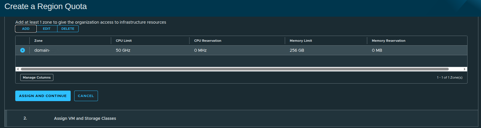
At this stage, the region quota includes:
- selected zone
- defined CPU and memory limits
- no reservations
Once applied, the organization now has access to infrastructure within controlled boundaries.
Why Quotas Matter #
Region quota is one of the most critical controls in VCF Automation.
From the Quick Start comparison:
- Quick Start assigns full capacity by default
- Manual setup allows precise control over consumption
Without quota:
- workloads cannot be deployed
With quota:
- consumption is controlled
- multi-tenant boundaries are enforced
- capacity planning becomes predictable
Defining Consumption: VM Classes and Storage #
With the region and quota in place, the next step is defining how workloads will actually consume resources.
This is done through:
- VM Classes (compute and memory sizing)
- Storage Classes (persistent storage consumption)
Selecting VM Classes #
VM Classes define the “t-shirt sizes” that users can request when deploying workloads.
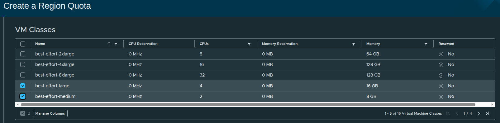
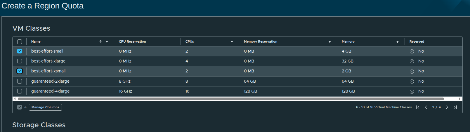
In this configuration, the following best-effort classes are selected:
- small
- medium
- large
- xsmall
These represent flexible, non-guaranteed resource allocations.
Why Best-Effort Matters #
Best-effort VM classes:
- do not reserve CPU or memory
- allow higher density on infrastructure
- are ideal for general-purpose workloads
In contrast, guaranteed VM classes require reservations, which must be defined earlier at the region quota level.
Since no reservations were configured in the quota:
Only best-effort VM classes are appropriate in this design.
This is an intentional choice to keep the platform flexible.
Assigning Storage Capacity #
Next, storage consumption is defined using storage classes.
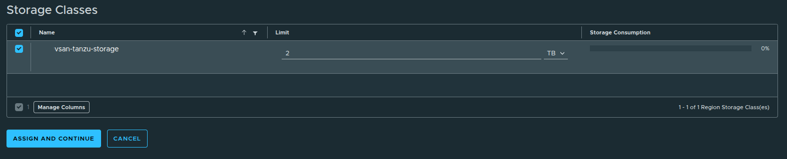
In this case:
- Storage Class:
vsan-tanzu-storage - Limit: 1 TB
Although more storage is available in the workload domain, the limit is intentionally restricted.
Why Storage Limits Matter #
Storage limits:
- prevent overconsumption by a single organization
- enforce fair usage across tenants
- align with real-world capacity planning
Quick Start would have assigned full access automatically.
Manual setup ensures:
storage consumption is controlled from the beginning.
Completing Resource Assignment #
Once VM classes and storage limits are defined, the configuration is applied.
At this stage:
- region quota is active
- VM classes are available
- storage limits are enforced
However, the organization still cannot deploy workloads externally.
Configuring IP Space #
The next step is defining how IP addresses are allocated to the organization.
An IP space provides a structured way to:
- allocate IP addresses to organizations
- prevent overlapping address usage
- control consumption through quotas
Creating the IP Space #
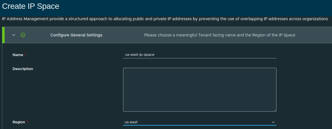
In this walkthrough:
- Name:
us-east-ip-space - Region:
us-east
This ties the IP space directly to the region created earlier.
Defining the IP Block #
The IP block defines the actual address range available to the organization.
- CIDR Block:
x.x.x.x/19
This becomes the pool from which:
- workloads receive IP addresses
- networks are carved out
External Reachability #
To allow connectivity beyond the organization:
- External Reachability:
0.0.0.0/0
This represents:
all external networks, including internet or upstream routing domains
Default Quota Settings #
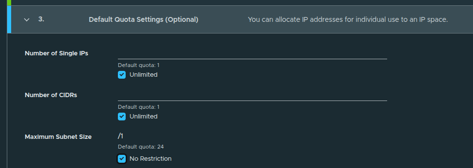
Default quotas are configured as:
- Single IPs: Unlimited
- CIDRs: Unlimited
- Maximum Subnet Size: No Restriction
This allows flexibility in how IP space is consumed.
These can be restricted later if tighter control is needed.
IP Space Created #
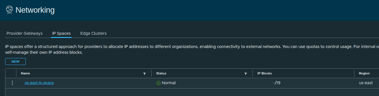
At this stage:
- IP space is defined
- address allocation is controlled
- region alignment is complete
Configuring External Connectivity and Regional Networking #
With IP space defined, the next step is enabling external connectivity and associating networking resources to the organization.
This is where the platform transitions from:
defined infrastructure to usable cloud platform
Creating the Provider Gateway #
A provider gateway enables northbound connectivity from the organization to external networks.
The provider gateway:
- connects organization networks to external networks
- leverages NSX Tier-0 gateways or VRFs
- associates IP spaces for routing and advertisement
In simple terms:
this is what allows workloads to communicate outside of the platform
Provider Gateway Configuration #
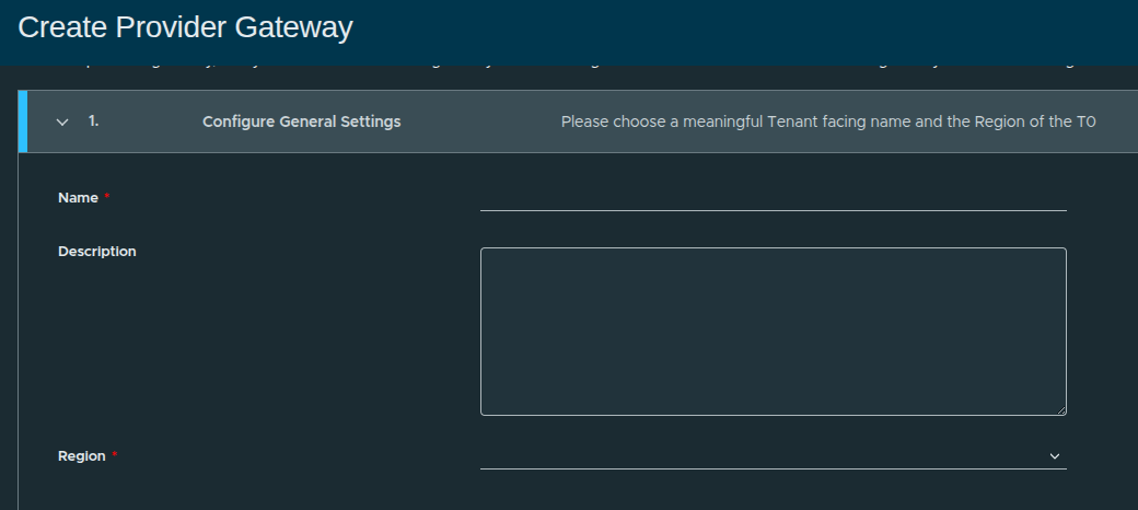
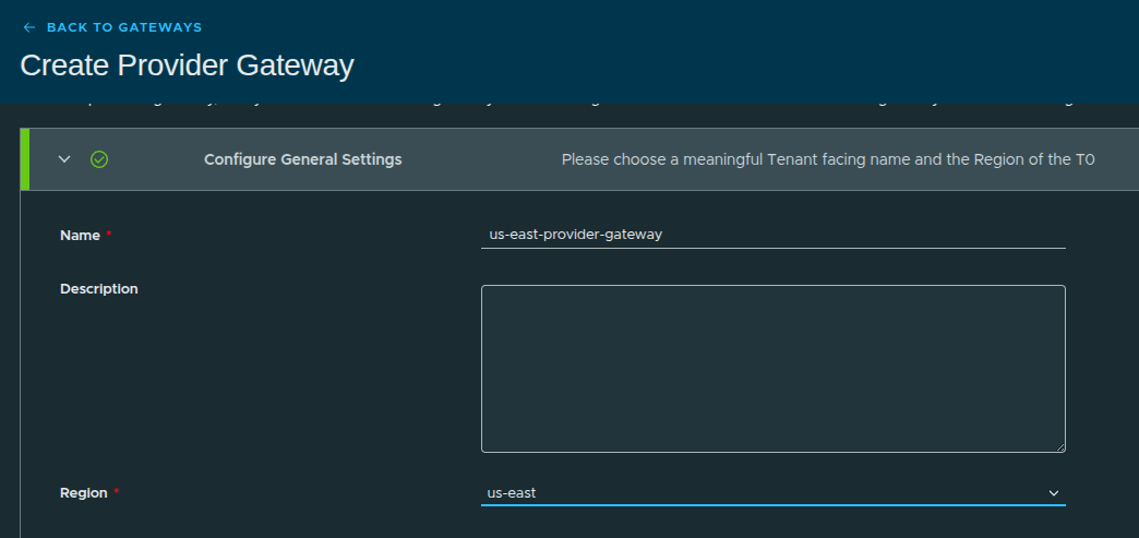
Configuration details:
- Name:
us-east-provider-gateway - Region:
us-east
Without a provider gateway:
- workloads cannot reach external networks
- IP space cannot be utilized for routing
- the platform remains isolated
With it:
- external connectivity is established
- routing is enabled
- real-world workloads become possible
Selecting the Tier-0 Gateway #
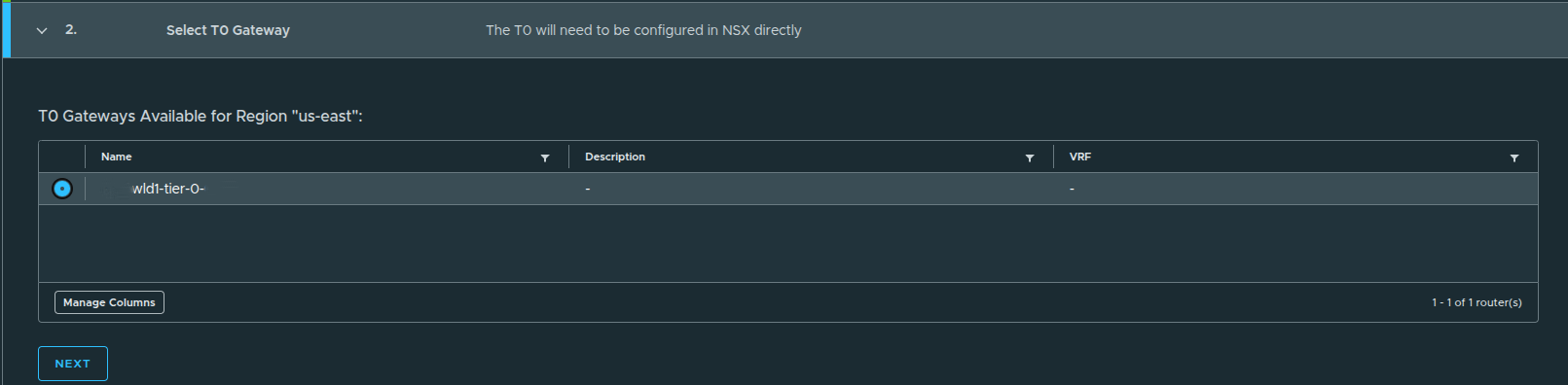
Here, the provider gateway is mapped to an existing NSX Tier-0 gateway:
wld1-tier-0
This Tier-0 is responsible for:
- routing traffic northbound
- advertising networks upstream
- providing external connectivity
Associating the IP Space #
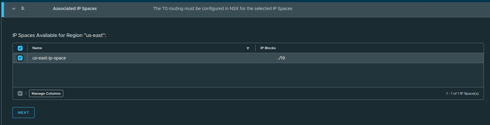
The previously created IP space is now linked:
us-east-ip-space
This ensures:
- IP addresses allocated to workloads are routable
- external connectivity aligns with defined IP blocks
Review and Create #
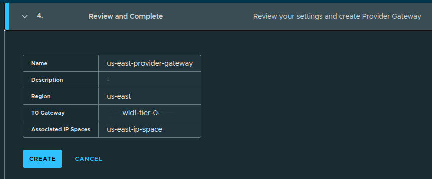
Once confirmed:
- the provider gateway is created
- it becomes available for assignment to organizations
Provider Gateway Created #
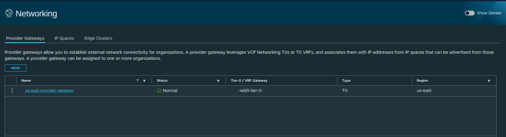
At this stage:
- external connectivity is defined
- IP space is integrated with routing
- the provider gateway is ready for use
Configuring Regional Networking #
With the provider gateway created, the final step is assigning networking resources to the organization.
Even with a provider gateway in place:
the organization cannot use it until it is explicitly assigned
This step defines:
- which provider gateways the organization can use
- where VPC networking will be deployed
- which edge clusters handle traffic
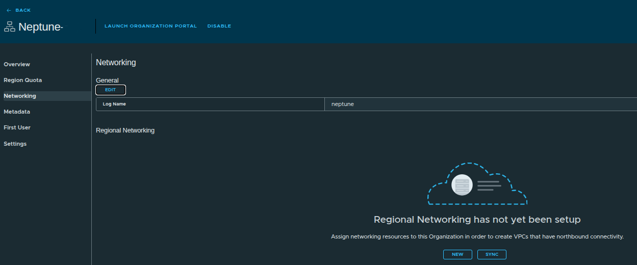
Initial Networking State #
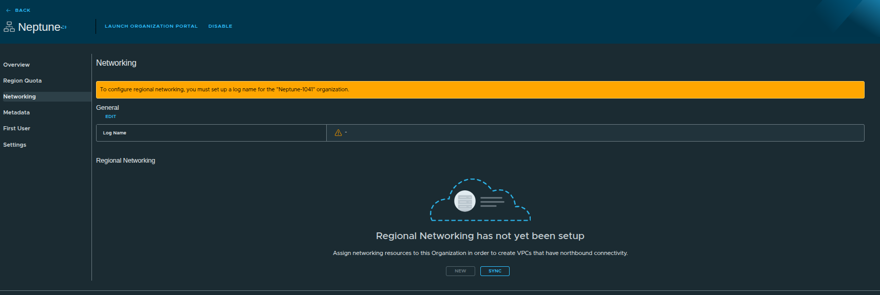
At this point:
- no networking is assigned
- workloads cannot deploy with external connectivity
Setting the Log Name #
Before configuring networking, a log name must be defined.
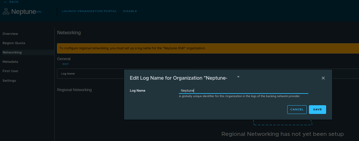
Example:
- Log Name:
neptune
The log name acts as:
- a globally unique identifier
- a filter for network logs
This becomes useful when:
- logs are forwarded to VCF Operations for Logs
- troubleshooting connectivity or routing issues
It allows you to quickly isolate logs belonging to a specific organization.
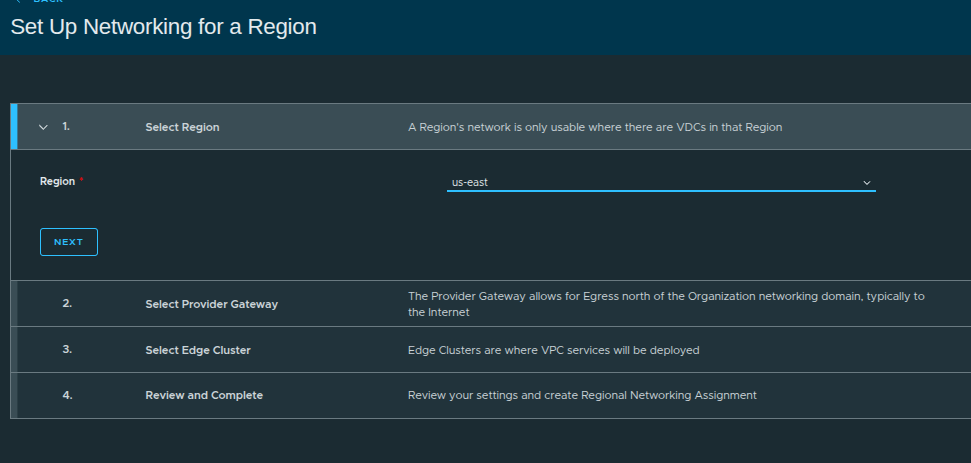
Starting Regional Networking Configuration #
Steps:
- Select Region (
us-east) - Select Provider Gateway
- Select Edge Cluster
- Review and complete
Selecting the Provider Gateway #
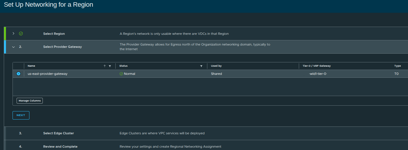
Here, we assign:
us-east-provider-gateway
This links the organization to:
- external routing
- IP space
- northbound connectivity
Selecting the Edge Cluster #
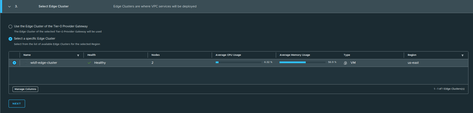
During regional networking setup, you are presented with two options:
- Use the edge cluster associated with the Tier-0 provider gateway
- Select a specific edge cluster
When to Choose Each Option #
Default Option (Used Here):
- Uses the edge cluster tied to the Tier-0 gateway
- Ideal for simple or single-edge environments
Manual Selection:
- Useful when multiple edge clusters exist
- Allows separation of:
- environments such as prod vs dev
- connectivity paths
- network services or use cases
In this example:
only one edge cluster exists, so the default selection is sufficient
Review and Create Regional Networking #
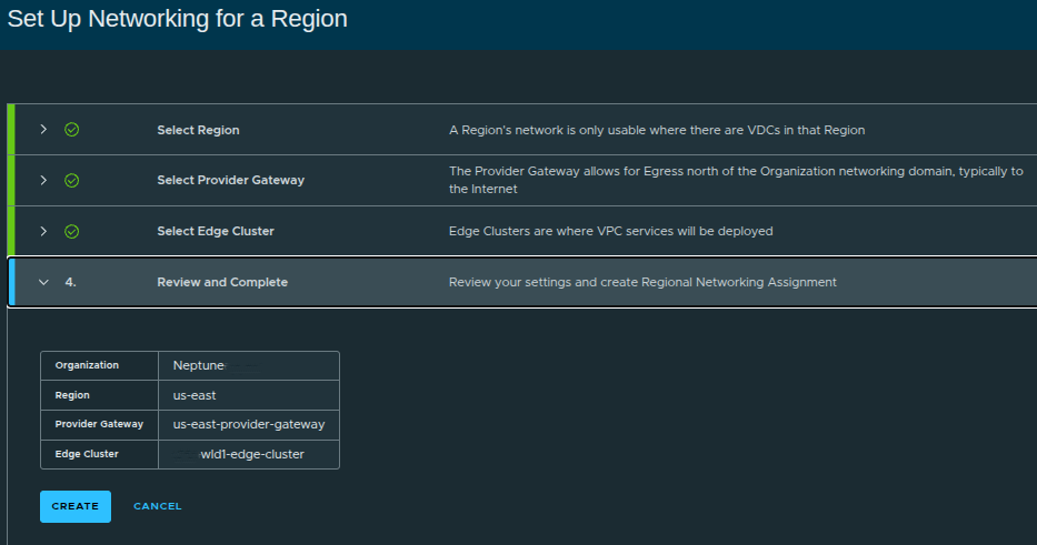
Configuration summary:
- Organization:
Neptune - Region:
us-east - Provider Gateway:
us-east-provider-gateway - Edge Cluster:
wld1-edge-cluster
Once created:
- networking is now fully assigned to the organization
- VPC-capable infrastructure is ready
Regional Networking Configured #

Now we can see:
- Region:
us-east - Provider Gateway assigned
- Edge Cluster assigned
- Status: Normal
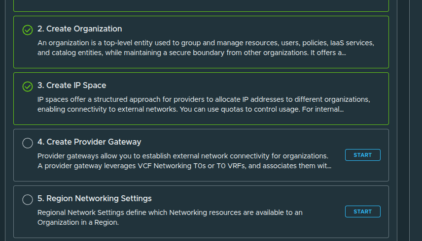
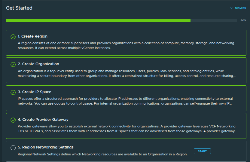
Platform Setup Complete #
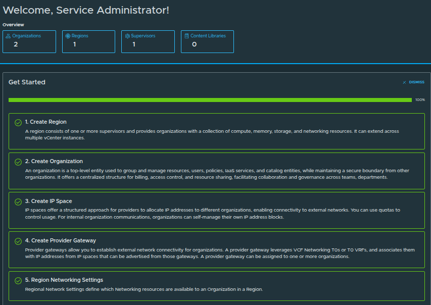
All steps are now complete:
- Create Region ✅
- Create Organization ✅
- Create IP Space ✅
- Create Provider Gateway ✅
- Region Networking Settings ✅
Creating the First User and Completing Provider Setup #
Before handing off the organization, a user must be created.
The first user acts as:
- the initial entry point into the organization
- a bootstrap administrator account
From here:
- identity providers such as AD, LDAP, or SAML can be configured
- additional users and roles can be created
Creating the Admin User #
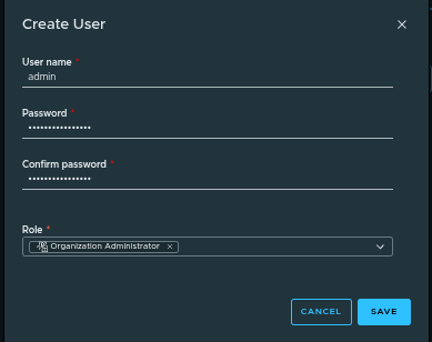
Example configuration:
- Username:
admin - Role: Organization Administrator
- Password: defined during creation
First User Created #
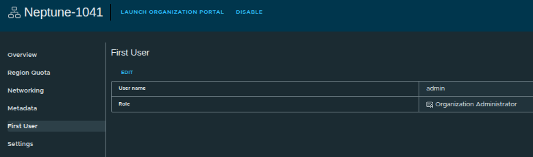
At this stage:
- the organization has an administrator account
- access can now be delegated
- the platform is ready for consumption
With everything configured, the organization can now:
- access the Organization Portal
- deploy workloads via VCF Automation
- create VPCs and networked applications
- consume compute, storage, and networking resources
- integrate identity providers for user management
Final Configuration, Validation, and Accessing the Organization #
At this stage, the manual provider-side setup is complete. The region, organization, quotas, IP space, provider gateway, regional networking, and first user have all been configured.
That means the platform is no longer just defined at the infrastructure layer. It is now ready to be validated from the organization perspective and handed off for actual consumption.
By walking through this process manually, you gain:
- full control over infrastructure design
- visibility into networking and resource allocation
- a clearer understanding of how NSX, IP spaces, provider gateways, and organization services fit together
While automated workflows can simplify deployment:
mastering the manual process ensures you understand exactly how the platform operates under the hood
Enabling Content Library Permissions #
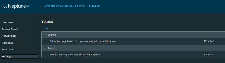
Before handing off to the organization administrator, we enable an important setting:
- Allow this organization to create subscribed content libraries
If this is disabled:
- org admins can only create local content libraries
- images must be uploaded manually
If this is enabled:
- org admins can subscribe to external content libraries
- enables centralized image distribution across environments
This setting directly impacts how scalable and automated image management will be for the tenant.
Launching the Organization Portal #
There are two ways to access the Organization Portal:
- From the Provider UI
- Using the direct organization URL
Once launched:
- the org admin is dropped into the VCF Automation interface
- this is where all day-to-day operations happen
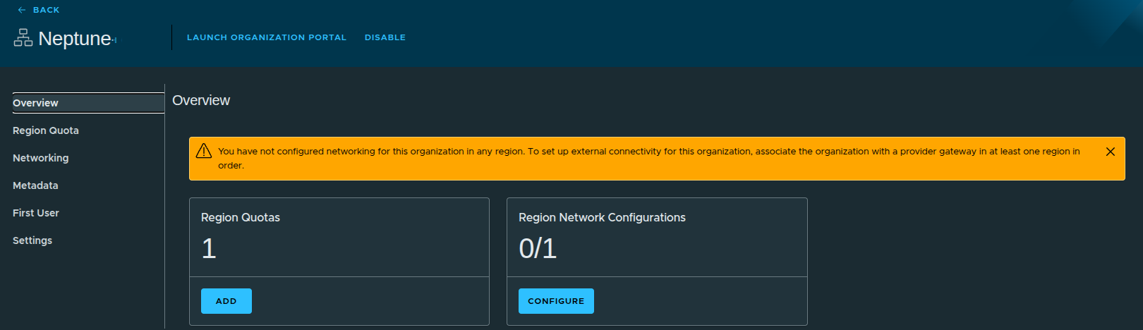
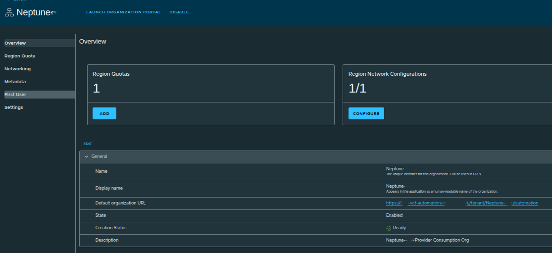
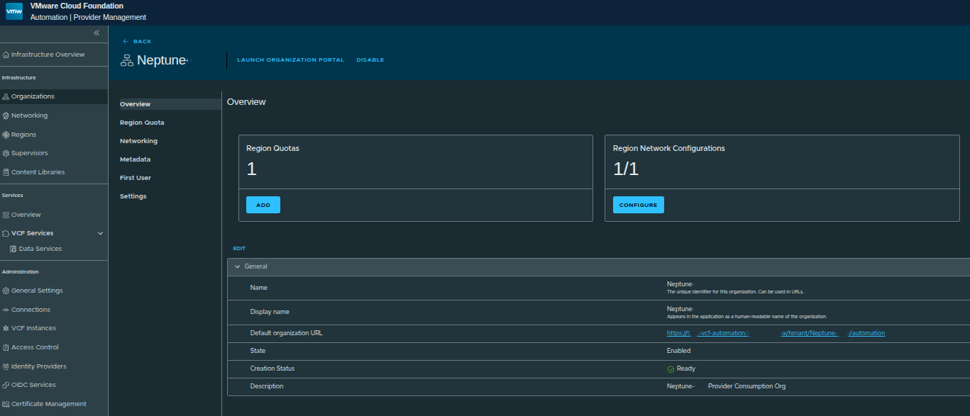
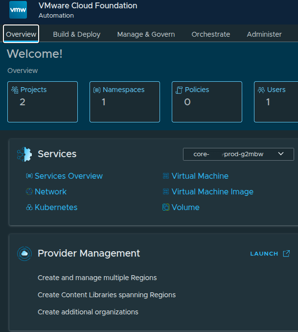
Organization Portal Overview #
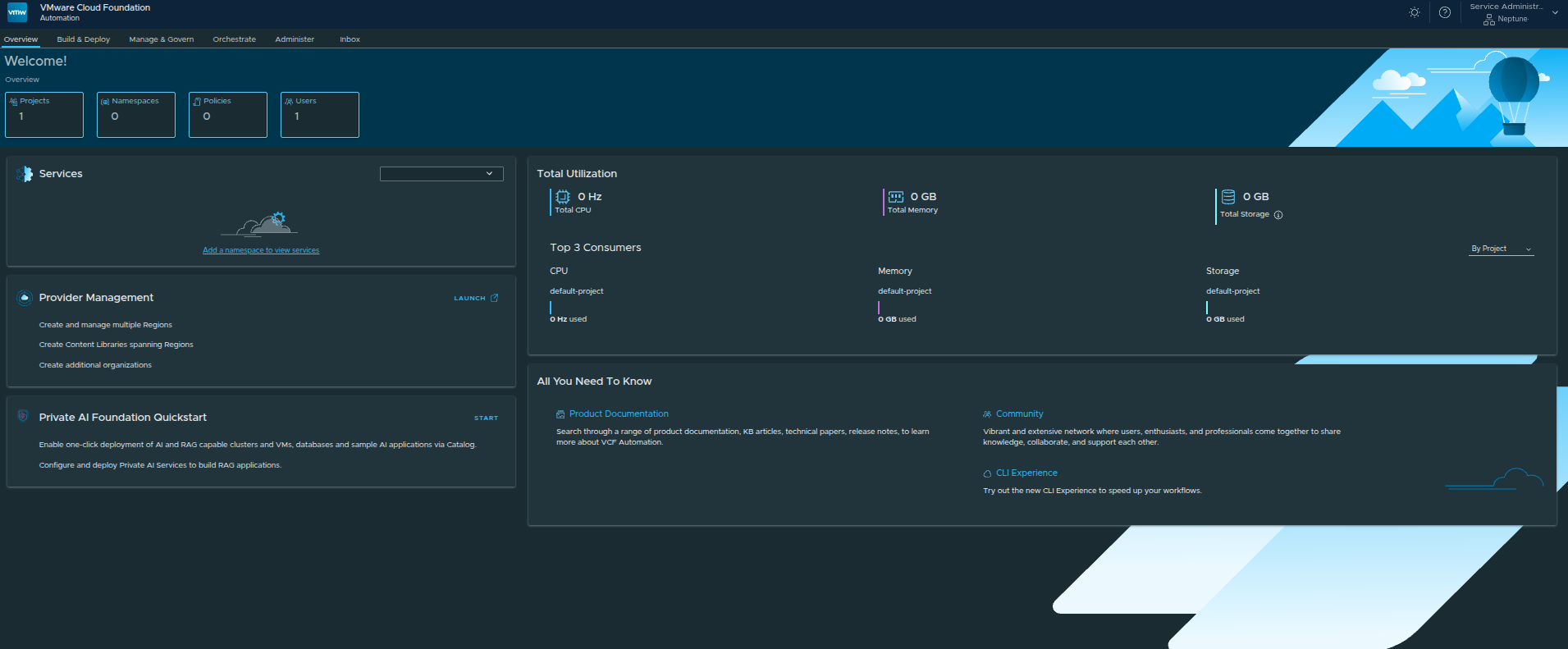
From here, the organization administrator can:
- manage projects and namespaces
- deploy workloads
- monitor resource consumption
- configure policies and governance
At this point:
the platform is no longer just configured. It is operational.
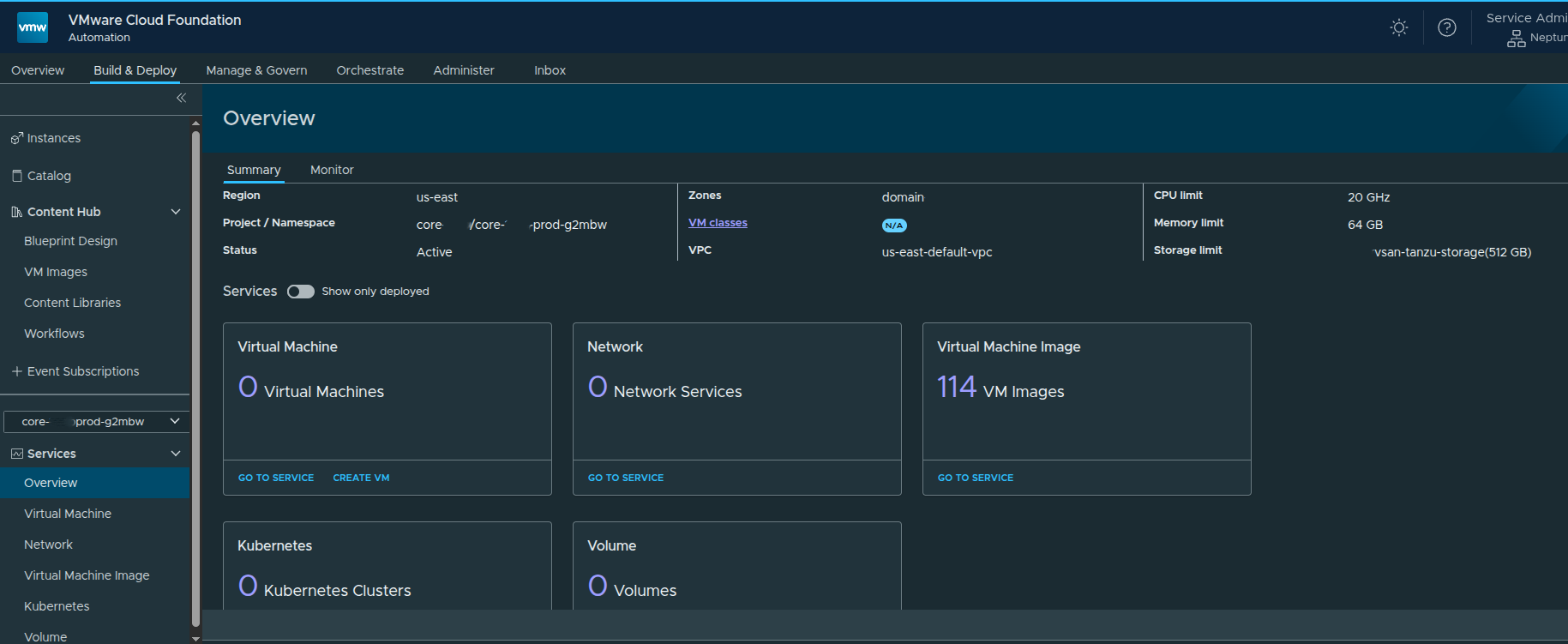
Validating Infrastructure Availability #
Within the Organization Portal, we can confirm:
- Regions are available
- Resource quotas are applied
- Networking is functional
- Default VPCs are automatically created
This validates that:
- provider-side configuration successfully propagated to the tenant
- the organization is ready for workload deployment
The next requirement is enabling workload deployment through VM images.
VCF Automation requires at least one content library to:
- store VM templates such as OVA or OVF
- provide ISO images
- enable Virtual Machine Service deployments
Creating a Local Content Library #
To enable workload deployment, we now create a local content library within the organization.
Navigating to Content Libraries #
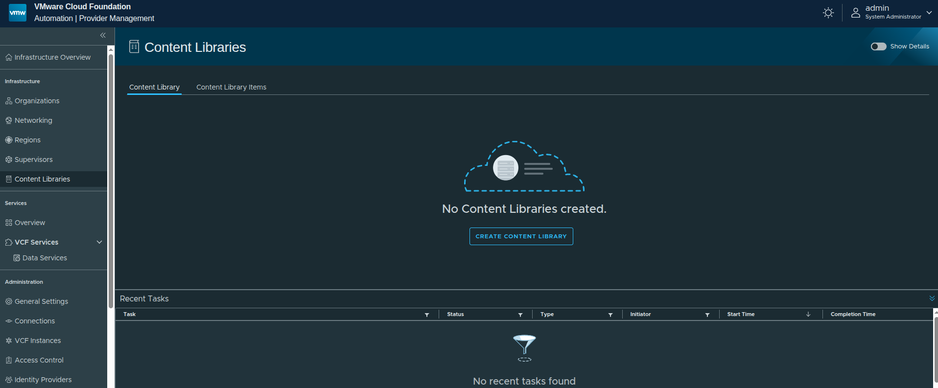
Creating the Content Library #
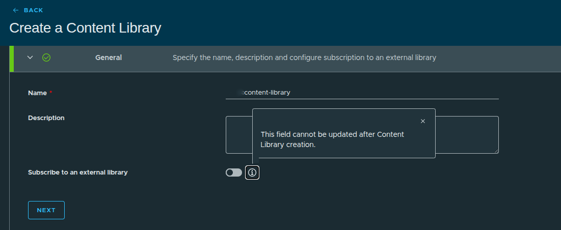
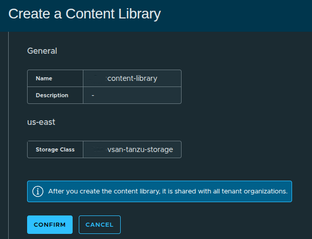
Configuration:
- Name:
content-library - Description: optional
- Subscribe to external library: Disabled
Why Local Instead of Subscribed? #
In this setup:
- we are not integrating with an external published library
- images will be uploaded manually
This approach is useful when:
- working in air-gapped environments
- no external repository is available
- images must be controlled locally
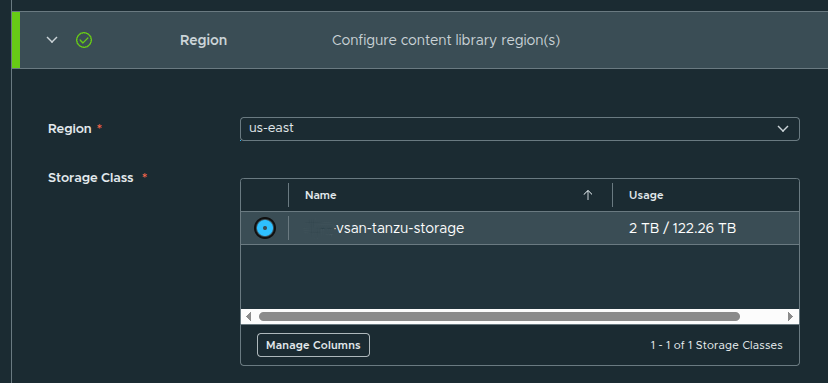
Assigning Region and Storage #
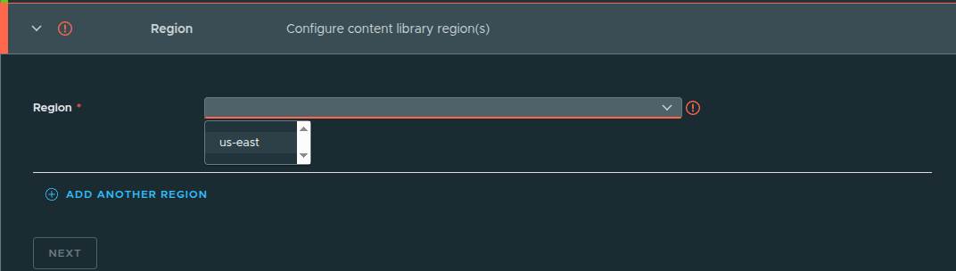
Configuration:
- Region:
us-east - Storage Class:
vsan-tanzu-storage
This determines:
- where images are stored
- which workloads can consume them
Review and Create #
After confirming settings:
- click Confirm
- the content library is created
Content Library Created #
At this point:
- the library exists
- but contains no images yet
To make this usable:
- upload VM images such as OVA, OVF, or ISO
- or later integrate with a subscribed library
Once populated, the Virtual Machine Service can deploy workloads using these images.
Creating a Namespace Class #
Now that we have the content library configured and images available to the Virtual Machine Service, the next step is to define how resources will be consumed within the organization.
This is done through Namespace Classes.
What Is a Namespace Class? #
A Namespace Class acts as a template that defines:
- CPU and Memory limits
- Storage allocations
- Allowed VM classes
- Available content libraries
These templates are later referenced when creating namespaces, ensuring consistency and governance across deployments.
Navigating to Namespace Classes #
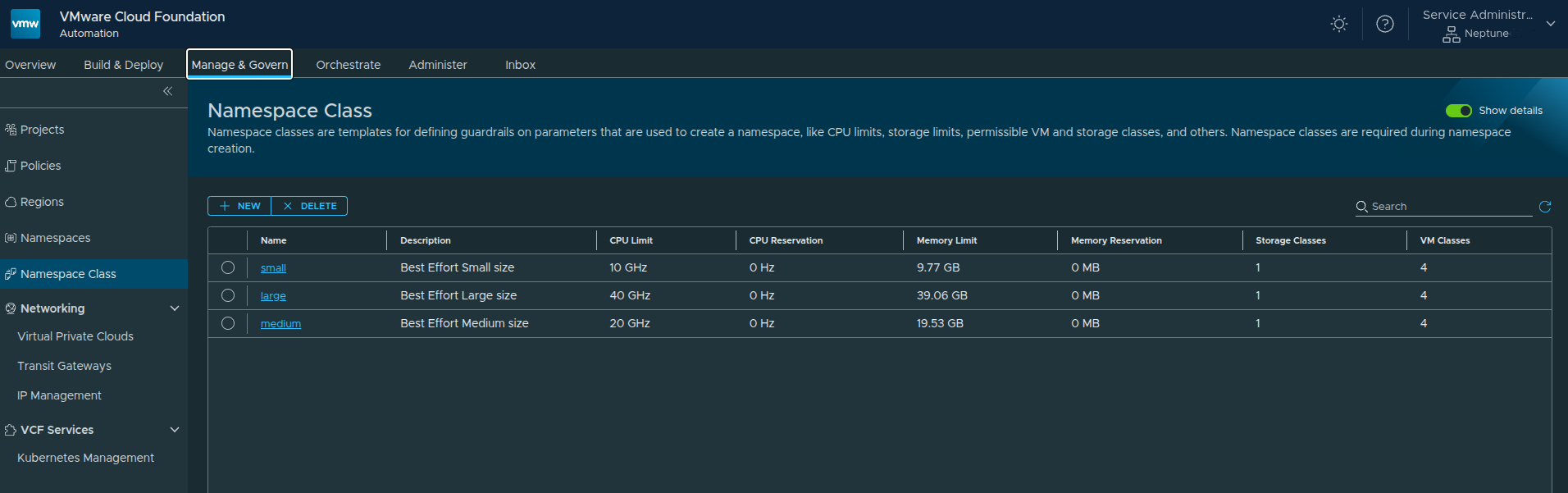
Path:
Manage and Govern → Namespace Class
Out of the box, you will see default templates such as:
- small
- medium
- large
These are preconfigured based on the resources allocated to the organization.
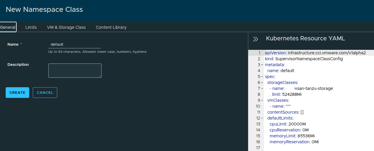
Creating a New Namespace Class #
Click New and define a custom class.
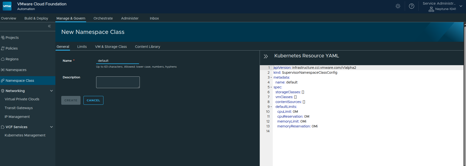
Configuration:
- Name:
default - Description: optional
On the right-hand side, you will notice a Kubernetes Resource YAML representation.
This reflects how the Namespace Class is defined at the Supervisor level.
Configuring Resource Limits #
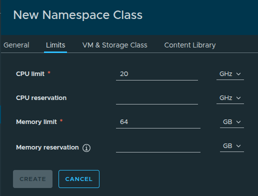
Here we define default resource constraints:
- CPU Limit:
20 GHz - Memory Limit:
64 GB
These values are derived from the total available resources allocated earlier:
- ~50 GHz CPU
- 256 GB Memory
This ensures namespaces created from this class do not overconsume available resources.
Selecting VM Classes #
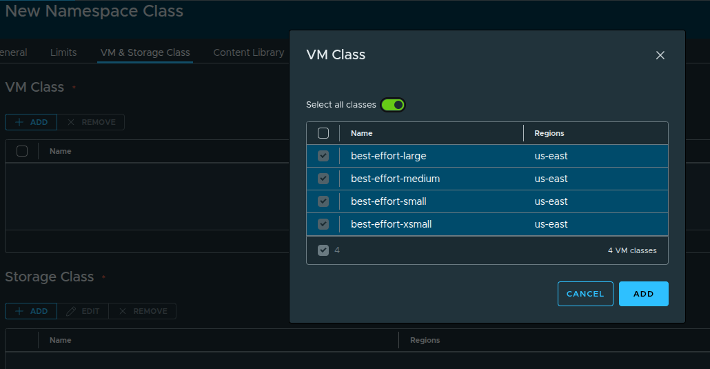
Next, select the VM classes that can be used within this namespace class.
In this setup, we select:
- best-effort-small
- best-effort-xsmall
- best-effort-medium
- best-effort-large
These were previously granted to the organization by the provider.
Important: Ensure VM classes are available across the regions you plan to use.
Configuring Storage #
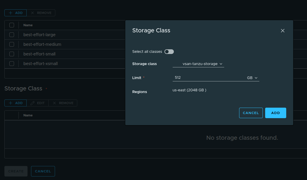
Select the storage class and define limits:
- Storage Class:
vsan-tanzu-storage - Limit:
512 GB
This storage is consumed from the region-level allocation:
- 1 TB in
us-east
Content Library Behavior #
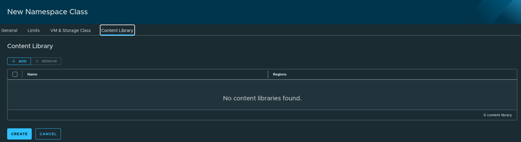
In this step, you may notice:
No content libraries are displayed.
This is expected.
Because the content library was configured with auto-attach, it is:
- automatically available to all namespaces
- does not need to be explicitly selected here
Reviewing the Configuration #
Returning to the General tab shows the full configuration:
- VM classes = all selected
- Storage class defined
- Resource limits applied
You can also:
- export the YAML
- reuse it for automation or CLI deployments
Creating the Namespace Class #
Once everything is configured:
- Click Create
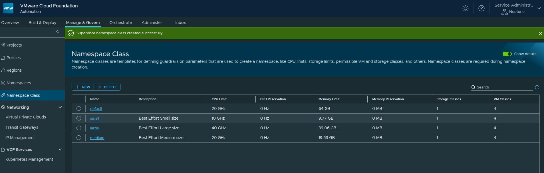
The new Namespace Class is now available and ready to be used.
Creating a Project and Namespace #
With the organization, networking, content library, and namespace class now in place, the next step is to begin consuming those resources by creating a project and namespace.
This is where the platform starts becoming usable for application teams. Projects provide a logical boundary for users and resources, while namespaces apply the compute, storage, and networking policies defined earlier through the namespace class.
Creating a Project #
Before creating a namespace, a project must exist.
Projects are used to:
- represent a team, application, or environment
- associate users with resources
- enforce access and consumption boundaries
Default Project #
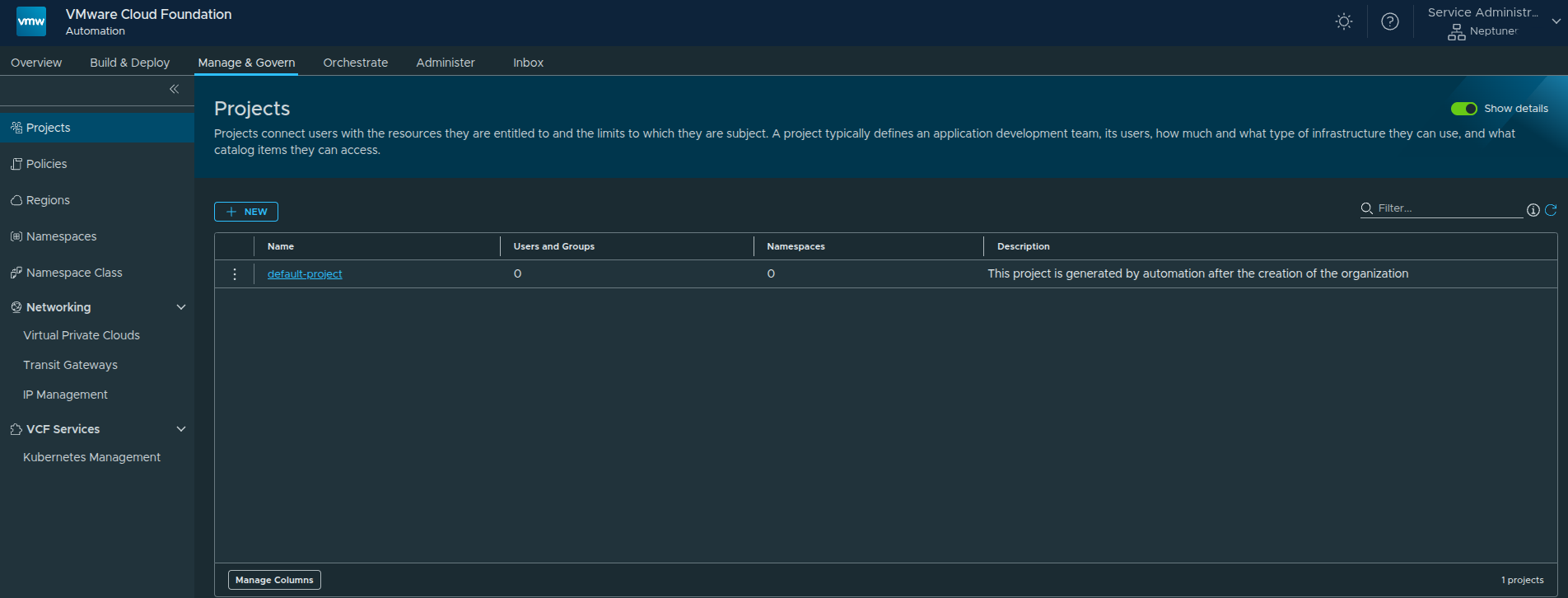
A default project is automatically created when the organization is enabled.
However, for this walkthrough, we will create a new project.
Creating a New Project #
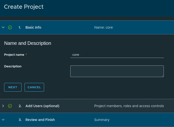
Configuration:
- Project Name:
core - Description: optional
User assignment:
- Skipped for now because no identity provider is configured yet
At this stage, only the built-in admin user exists.
Creating a Namespace #
Once inside the project, we can create namespaces.
A Namespace is where:
- workloads are deployed
- resources are consumed
- services become available
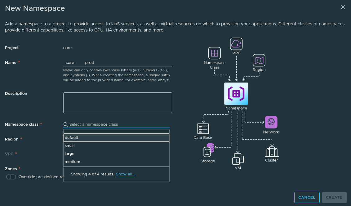
Namespace Configuration #
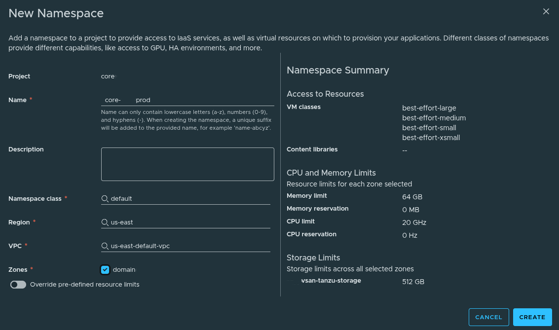
Example configuration:
- Name:
core-prod - Namespace Class:
default - Region:
us-east - VPC:
us-east-default-vpc - Zone:
domain
What This Does #
By selecting the Namespace Class, the namespace automatically inherits:
- CPU Limit:
20 GHz - Memory Limit:
64 GB - Storage Limit:
512 GB - VM Classes:
- best-effort-small
- best-effort-xsmall
- best-effort-medium
- best-effort-large
Override Option #
You also have the ability to:
- override CPU and memory limits
This is useful for:
- production workloads
- special use cases
In this walkthrough, we leave overrides disabled.
Creating the Namespace #
Click Create to deploy the namespace.
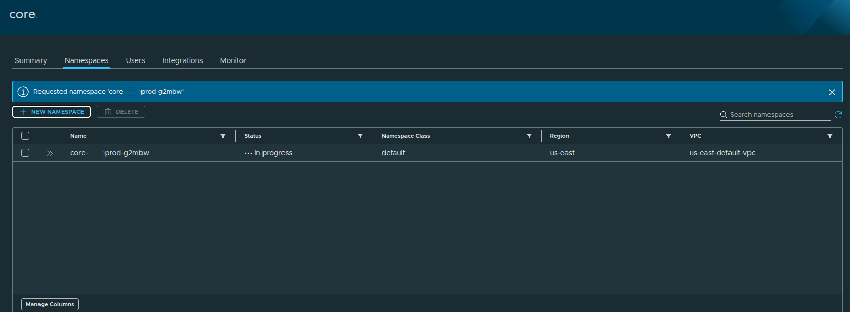
The namespace will initially show:
- Status:
In Progress
After a short period:
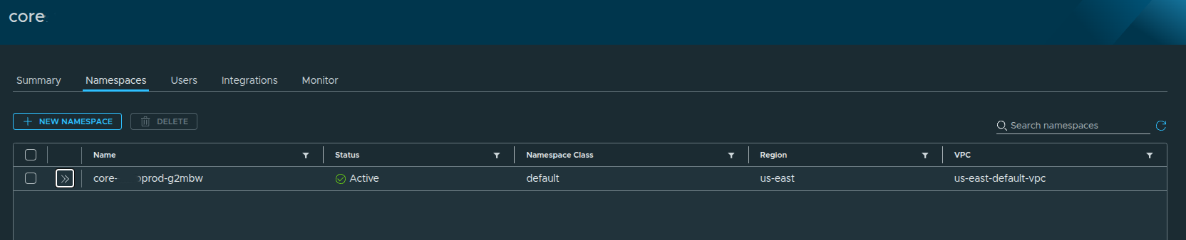
Status becomes:
- Active
Namespace Details #
Expanding the namespace shows:
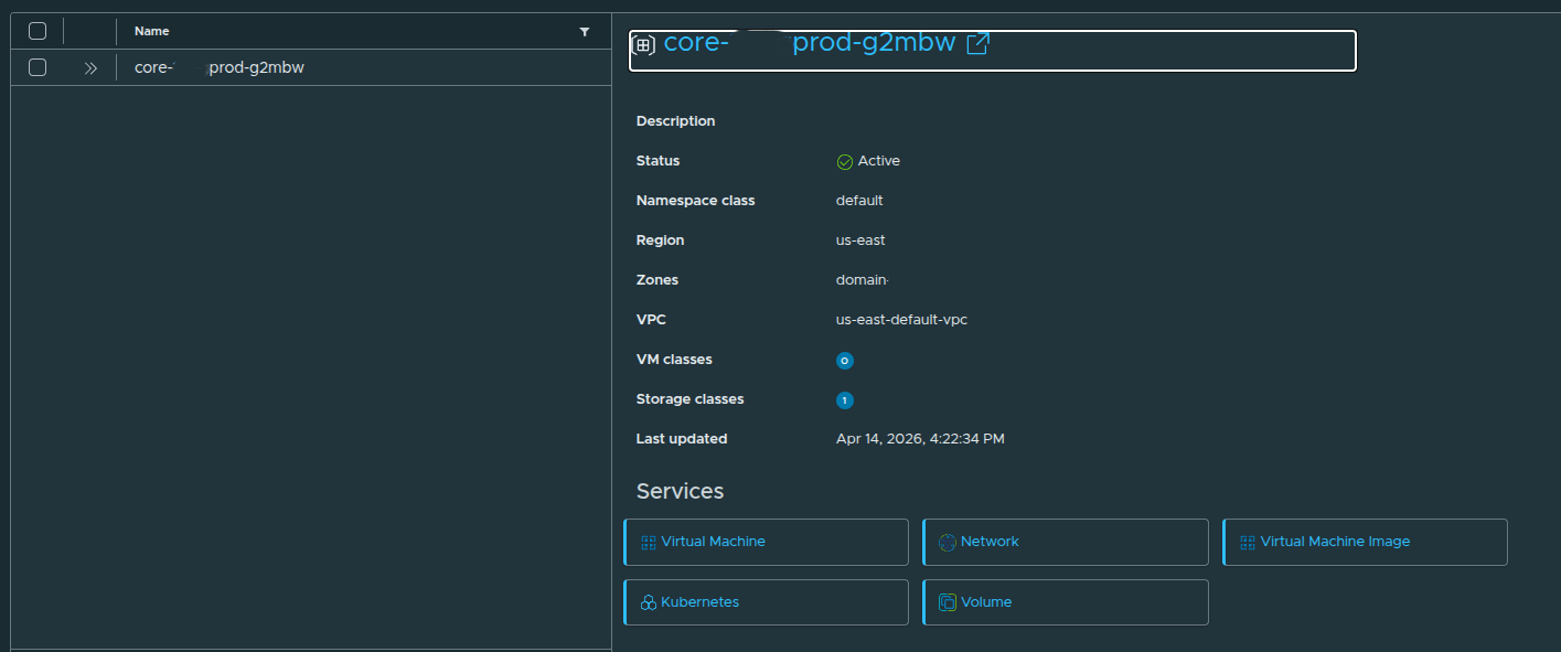
- Namespace Class: default
- Region: us-east
- VPC: us-east-default-vpc
- Zone: domain
And available services:
- Virtual Machine
- Network
- Kubernetes
- Volume
- Virtual Machine Image
Accessing Services #
Once active, the namespace becomes selectable in the UI:
You can now:
- switch between namespaces
- deploy workloads
- access services
Final Result #
At this point:
- Namespace is active
- Resources are allocated
- Services are available
You are now ready to:
- deploy virtual machines
- create Kubernetes clusters
- consume storage and networking
Deploying a Virtual Machine Through the VM Service #
At this point, the platform is no longer just configured. The organization has a project, namespace, namespace class, content library, networking, and available services.
Now we can validate the end-to-end flow by deploying a virtual machine through the Virtual Machine Service.
This is where the earlier configuration starts to matter.
The namespace controls the resource boundaries.
The content library provides the image source.
The VM class controls sizing.
The storage class controls placement.
The VPC determines network connectivity.
Accessing the Virtual Machine Service #
From the namespace services overview, the available core services are displayed as service tiles.
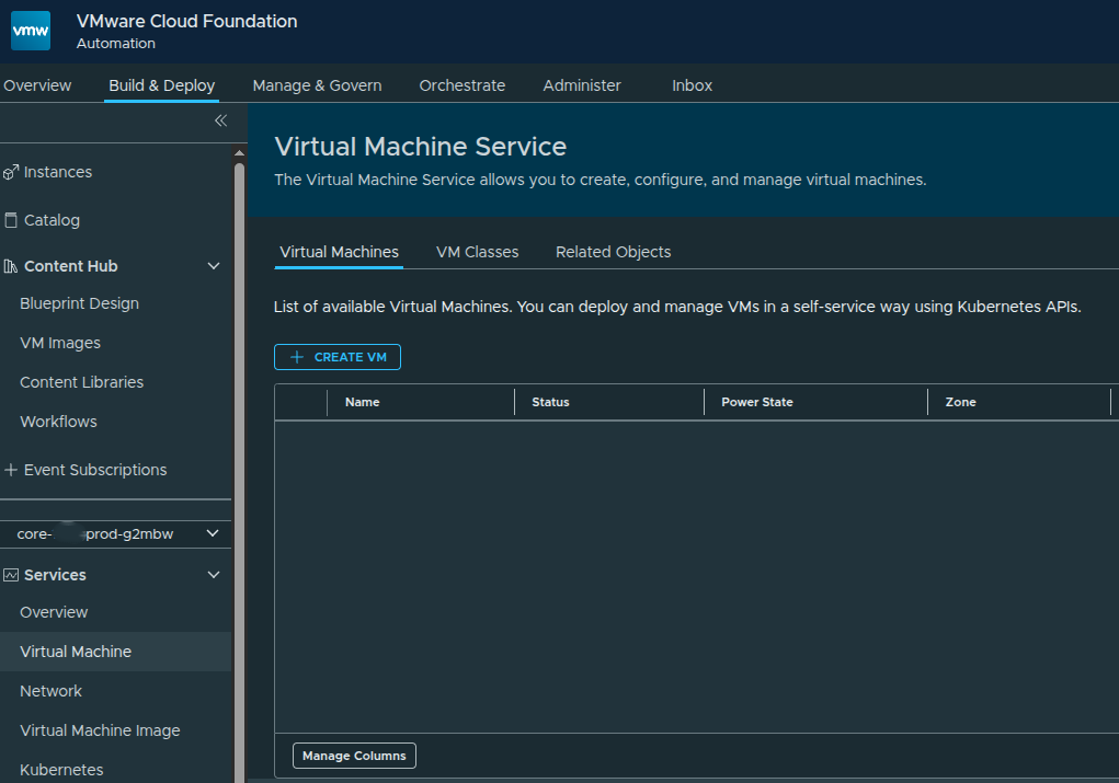
The core services available out of the box include:
- Virtual Machine
- Network
- Virtual Machine Image
- Kubernetes
- Volume
Additional services can appear here later as they are enabled, but these are the core services available after the namespace is active.
To deploy a virtual machine, we can either open the Virtual Machine service directly or use the Create VM action from the service tile.
Starting the New VM Workflow #
The Virtual Machine service provides a self-service interface for deploying and managing VMs inside the selected namespace.
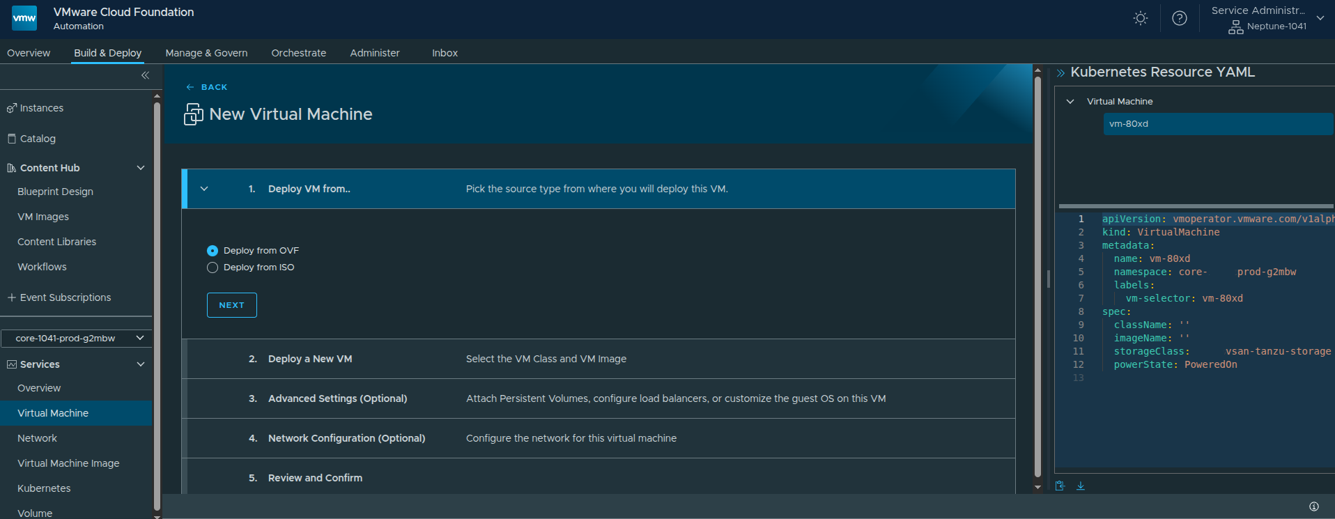
The workflow begins by selecting the source type.
VCF Automation supports:
- OVF
- ISO
For this example, I used OVF because it provides more deployment and configuration options than ISO-based provisioning.
Configuring the VM Basics #
The next step is defining the basic virtual machine configuration.
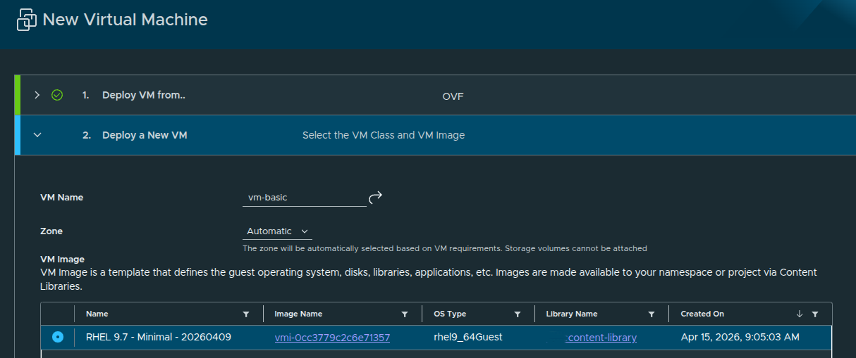
For this deployment, the configuration is intentionally simple:
- VM Name:
basic - Source Type:
OVF - VM Image: RHEL 9.7
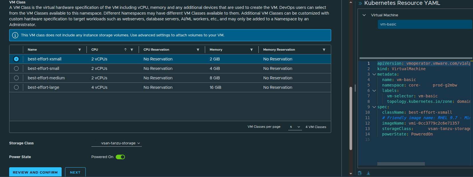
- VM Class:
best-effort-xsmall - Storage Class:
vsan-tanzu-storage - Power State: On
The selected VM class determines the virtual hardware profile. In this case, the best-effort-xsmall class provides:
- 2 vCPU
- 2 GB memory
- no CPU or memory reservation
This matches the best-effort consumption model that was made available through the earlier region quota and namespace class configuration.
Why Zone Selection Matters #
By default, the zone can be set to Automatic. That allows the platform to select the appropriate zone based on the VM requirements.
That is fine for a basic deployment.
However, there is an important caveat:
If you plan to attach additional storage volumes, select a specific zone instead of leaving placement on Automatic.
That matters because volume attachment requires the VM to be placed intentionally where the storage resources are available.
For a simple test VM, automatic placement is acceptable. For production workloads or anything using additional disks, I would be more explicit.
Configuring Guest Customization #
At this point, the VM could technically be deployed. However, cloud images such as RHEL 9.7 usually expect initial configuration to be provided during deployment.
The VM may deploy successfully, but you may not be able to log into it right away if guest customization is not configured.
RHEL cloud images are typically designed to work with cloud-init or a similar metadata-driven process to inject the initial user configuration. Without that, the VM may not have a usable password, SSH key, or enabled login path.
That is why guest customization matters.
At a minimum, I configured:
- time zone
- default user
- SSH access
- public SSH key injection
This ensures the VM is usable after deployment instead of simply powering on with no practical way to access it.
Advanced Settings and Bootstrap Configuration #
The guided inputs make it easier to configure the guest operating system without manually writing the full YAML from scratch.
In this example, the default user is enabled and SSH is configured so the VM can be accessed after deployment.
The workflow also exposes a bootstrap section, which allows commands to run during the initial VM startup.
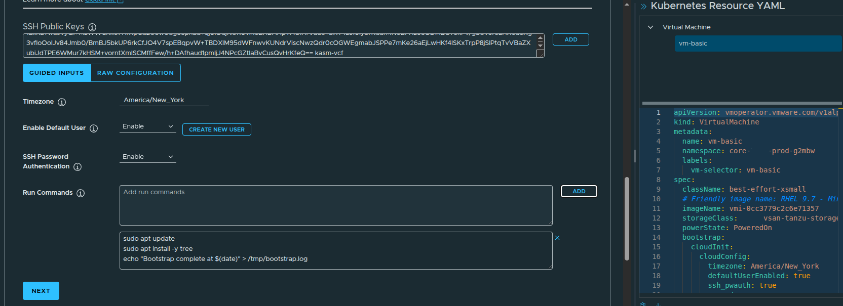
For a RHEL 9.7 image, bootstrap commands are useful for lightweight initialization tasks such as:
- refreshing package metadata
- installing baseline utilities
- writing a simple completion log
- preparing the VM for first use
This is not meant to replace full configuration management, but it is useful for validating that guest customization is working properly.
YAML Generation Behind the Scenes #
One of the more useful parts of the workflow is that VCF Automation generates the Kubernetes resource YAML as the VM is configured.
This matters because the UI is not the only way to deploy.
The generated YAML can be:
- copied
- downloaded
- stored in source control
- modified for repeatable deployments
- used with CLI-based workflows or GitOps-style tools
That makes the UI useful not just as a deployment interface, but also as a way to learn the underlying declarative model.
Configuring the VM Network #
The next step is configuring networking.
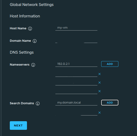
By default, the VM network interface may be connected to a private VPC subnet. That can work for internal-only workloads, but it may not be reachable from the network where you are testing.
This is also where DNS settings can be configured, including:
- domain name
- search domain
- DNS servers
This step is important because a VM can deploy successfully and still be difficult to use if network reachability or name resolution is wrong.
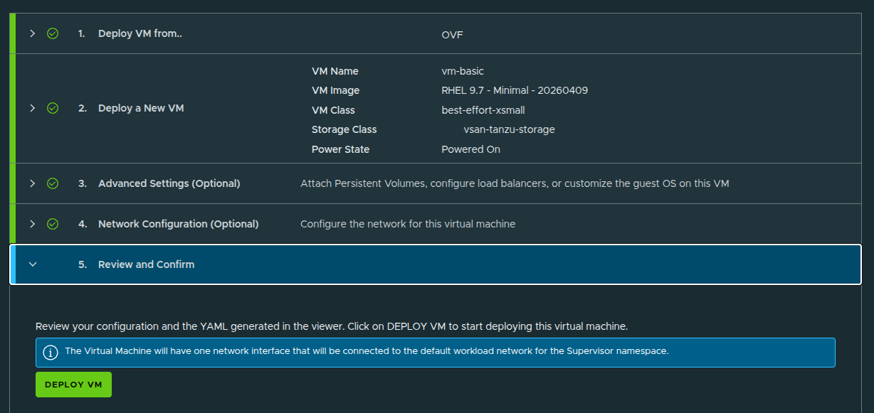
Reviewing and Deploying the VM #
After the VM configuration is complete, the workflow presents a final review before deployment.
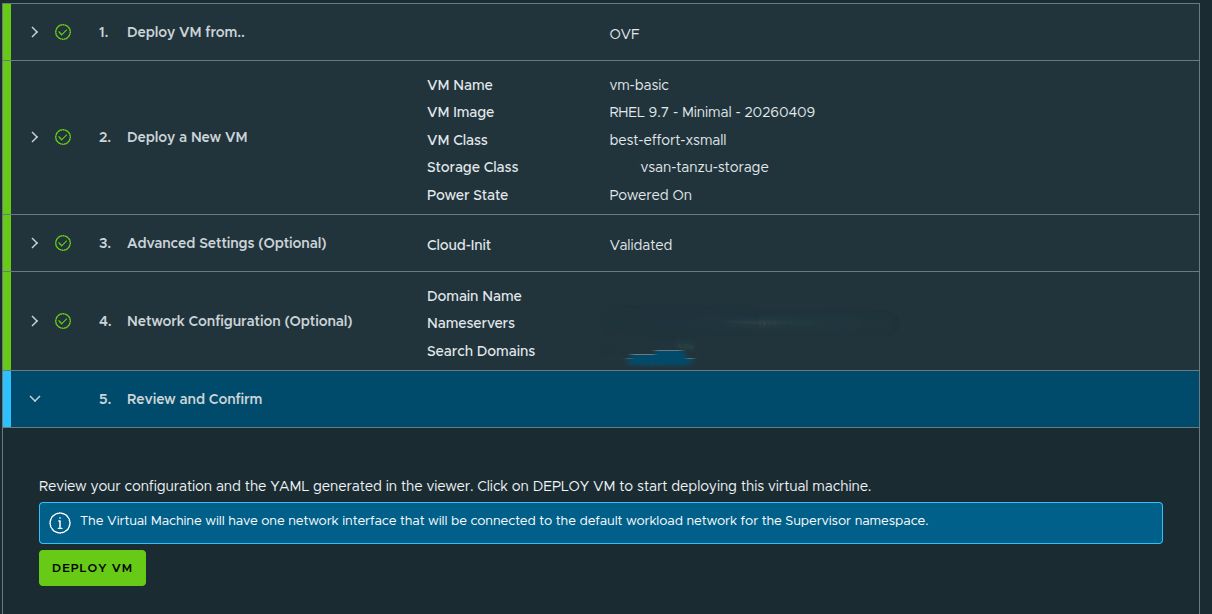
At this stage, the deployment is ready to submit.
Once confirmed, VCF Automation begins creating the VM from the selected OVF image and applies the configuration defined in the workflow.
This includes:
- VM image selection
- VM class sizing
- storage class placement
- guest customization
- SSH configuration
- network assignment
Validating the VM in vCenter #
Although the tenant or organization user would not normally need vCenter access, checking vCenter is useful from a provider or administrator perspective.
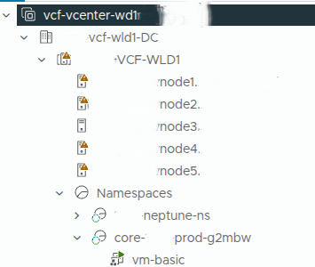
In vCenter, the VM appears under the namespace-backed inventory and begins deploying from the OVF template.
This confirms that the self-service request in VCF Automation is being translated into actual vSphere infrastructure activity behind the scenes.
That is an important validation point.
VCF Automation is not just showing a portal workflow. It is driving real infrastructure deployment through the platform services configured earlier.
Validating the VM in VCF Automation #
After the deployment completes, the VM appears in the Virtual Machine service.
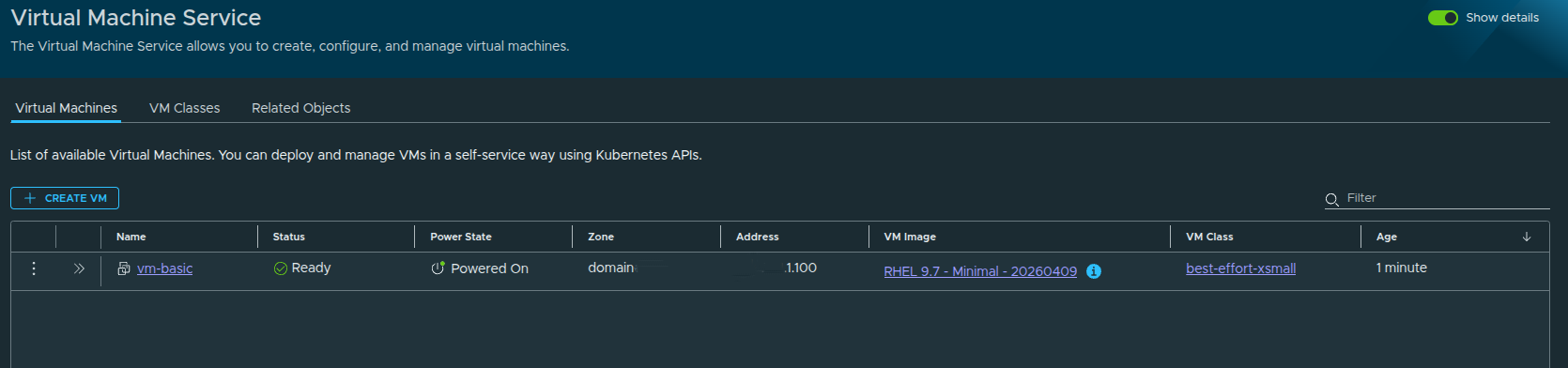
From this view, we can validate:
- VM status
- power state
- assigned IP address
- source image
- VM class
- namespace placement
The VM shows as ready and powered on, which confirms the end-to-end workflow completed successfully.
Day 2 Operations #
Once the VM exists, VCF Automation also exposes day 2 actions.
Depending on the VM state and permissions, these can include:
- power on
- power off
- console access
- VM class changes
- volume attachment
- reviewing network details
- viewing conditions and events
This is important because the platform is not only provisioning the VM. It is also giving the organization a controlled way to operate it after deployment.
What This Validates #
Deploying the VM validates the entire configuration chain.
A successful VM deployment confirms that:
- the organization is functional
- the namespace is active
- the namespace class is applying limits correctly
- the content library is usable
- the VM image is available
- the VM class is available
- the storage class is available
- networking is working
- guest customization is being applied
This is the point where the platform moves from configuration to consumption.
Final Thoughts #
Building an All Apps Organization in VCF Automation is not just about creating an organization and clicking through setup screens.
The real value is understanding how each layer connects:
- the provider defines the infrastructure
- the organization consumes the assigned resources
- the project creates a logical boundary
- the namespace activates services
- the namespace class applies guardrails
- the content library provides deployable images
- the VM service turns all of that into self-service infrastructure
That is why manual setup matters.
Quick Start can help you understand the basic flow, but manual setup forces you to understand the platform. It gives you control over the design decisions that actually matter: capacity, storage, networking, image management, and workload consumption.
Once the VM is deployed successfully, the All Apps Organization is no longer just configured.
It is usable.